New Solid-State NMR Method for Protein Backbone Assignment
Introduction
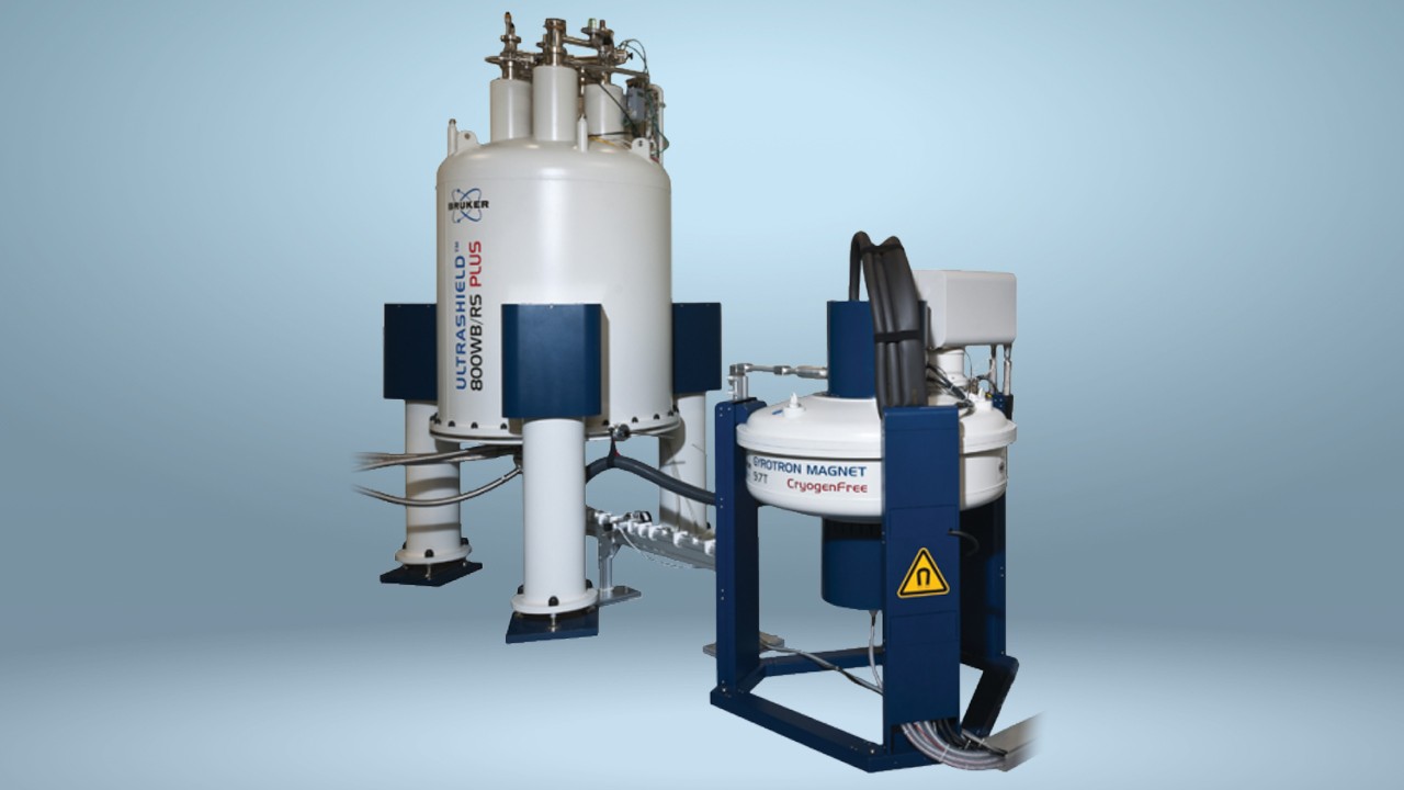
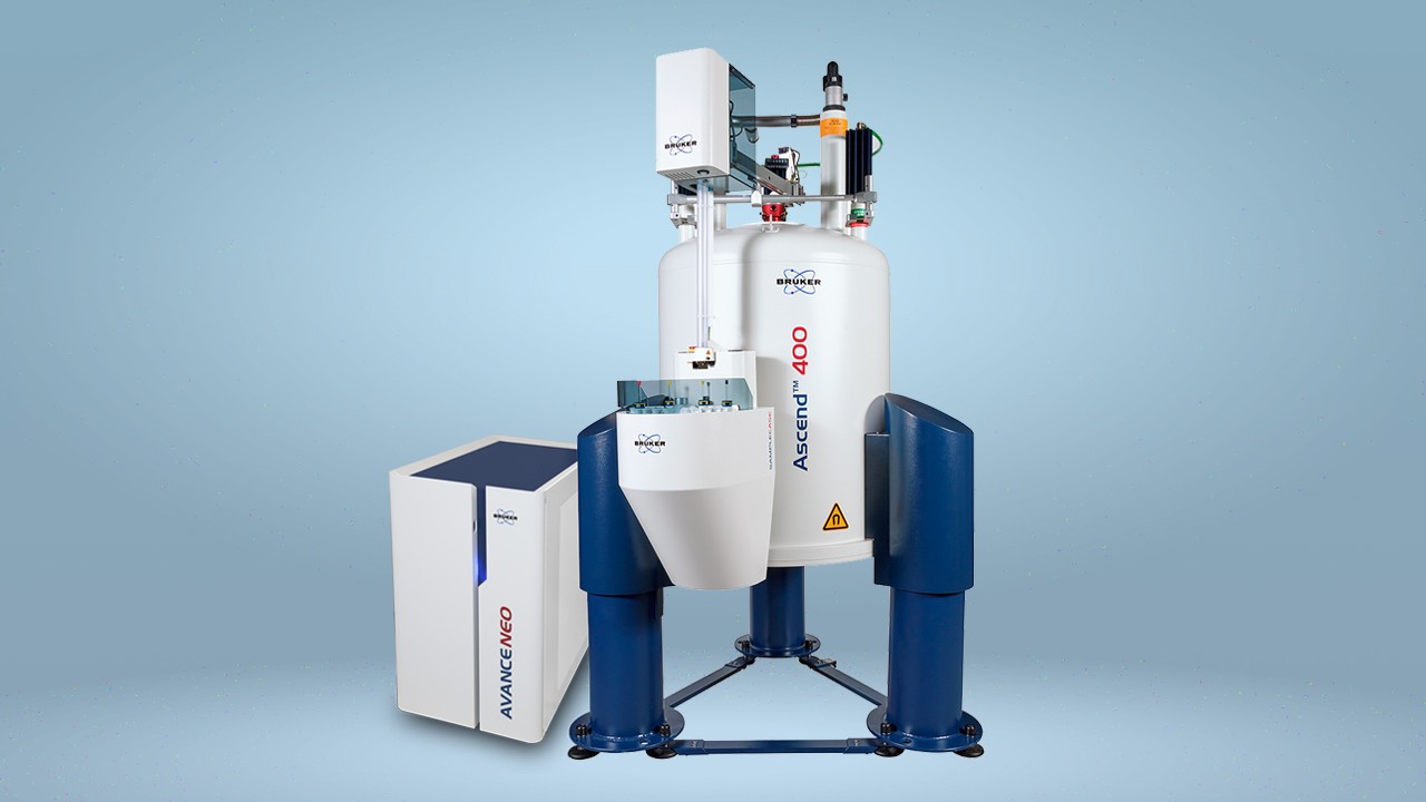
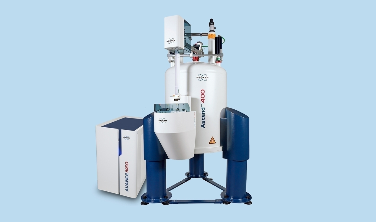
Solid-state nuclear magnetic resonance (NMR) spectroscopy has emerged as a well-established technique due to ongoing developments regarding higher magnetic fields (e.g. Bruker AVANCE 1000 MHz NMR spectrometer), advanced probe technology (e.g. ongoing development toward smaller rotor sizes to reach higher magic-angle spinning (MAS) rates), and selected pulse sequences.
A crucial step for solid state NMR site-specific protein characterization and structure elucidation is the time- consuming resonance assignment. The most common 2D and 3D experiments for intra- as well as inter-residue assignment use homonuclear 13C-13C dipolar recoupling sequences (e.g. proton-driven spin diffusion (PDSD [1, 2]) or dipolar assisted rotational resonance (DARR [3])) as well as specific heteronuclear 15N-13C magnetization transfer [4] combined with 13C-13C transfer (e.g. NCαCx, NCOCx).
In the latter case, the magnetization transfer from Cα to CO within one amino acid residue ‘i’ as well as from the CO of a given residue ‘i’ to Cα of the preceding residue ‘i-1’ is essential for protein backbone assignment (Figure 1).
Previously, this homonuclear 13C-13C transfer was mainly done by adding a dipolar-recoupling sequence, such as PDSD or DARR, to the specific NCx sequence. Recently, Adam Lange and co-workers introduced the robust and highly efficient dipolar-based band-selective homonuclear cross polarization (BSH CP) to transfer magnetization between CO and Cα spins.[5-7]
The technique is of special interest for deuterated as well as protonated proteins that can be measured at moderate MAS rates only (e.g. due to lack of a probe with small rotor diameter size, limited signal-to-noise ratio, etc.).
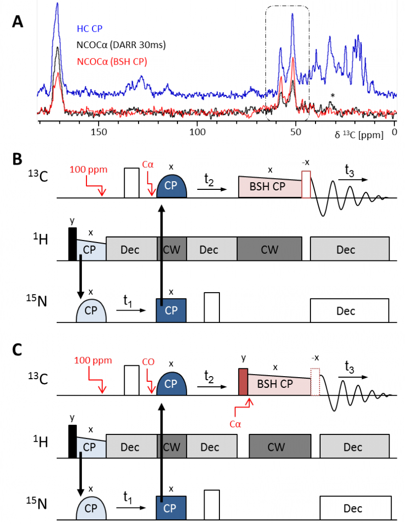
As a first-order recoupling mechanism, BSH CP efficiently suppresses unwanted sequential and long-range CO-Cα and Cα-Cα magnetization transfer by dipolar truncation. Furthermore, no undesirable transfer to Cβ resonances appears as it would in the conventional NCxCx sequences (compare with Figure 2A). Reasonable 3D experiments can be recorded within just one day. [5-7]
This article (and supporting Application Note) presents a set of BSH CP experiments to facilitate the recording of spectra and to simplify the assignment process. A detailed description of necessary parameters is given.
BSH CP – Experiments
In cooperation with Adam Lange and coworkers, Bruker offers five different BSH CP pulse programs (‘ppg’) from 1D up to 4D:
- 1D-3D hNCαCO (Figure 2B, ppg: ‘hNCaCO3D.bsh’)
- 1D-3D hNCOCα (Figure 2C, ppg: ‘hNCOCa3D.bsh’)
- 1D-4D hNCOCαCβ (Figure 3A, ppg: ‘hNCOCaCb4D.bsh’)
- 1D-4D hCαNCOCα (Figure 3B, ppg: ‘hCaNCOCO4D.bsh’)
- 1D-3D hCα(N)COCα (Figure 3B, ppg: ‘hCa_n_COCa3D.bsh’)
While the hNCαCO is the only experiment providing intraresidue correlations, all other sequences deliver sequential interresidue correlations (Figure 1). The two last experiments contain two specific double CP transfer steps to correlate vicinal Cα resonances with each other.
With the combination of these experiments, a fast protein backbone assignment is possible that can be combined with further experiments to elucidate the secondary and tertiary protein structure.
BSH CP – Pulse Sequences
In general all BSH CP experiments follow the same pulse sequence architecture (Figures 2B, C & 3). The initial magnetization derives from a 90° excitation pulse on 1H (black) followed by the initial CP transfer (light blue). While in the first three experiments this is a H-N polarization transfer, experiments four and five use a H-Cα CP. In any case the initial CP is followed by a specific double CP transfer (dark blue), either from N to Cα or CO or from Cα to N. In experiments four and five a further specific double CP, from N to CO, follows (Figure 3B, purple).
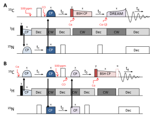
Finally, the homonuclear C-C transfer is achieved by the BSH CP (light red), either from Cα to CO or from CO to Cα. The hNCOCαCβ experiment comprises another homonuclear transfer to correlate Cα of a residue with its side chain Cβ atom. Here, a DREAM (Dipolar Recoupling Enhancement through Amplitude Modulation, [8]) transfer using a ramped shape has been proven to be most efficient (Figure 5B).[7]
During the evolution times (t1 – t4) high power 1H decoupling is used (light gray). During specific double CP and BSH CP transfers, continuous wave (CW, dark gray) 1H decoupling is active. JCN decoupling is provided by centered 180° 13C or 15N pulses during evolution times and low power 15N decoupling during acquisition.
Finally there are two important trim pulses. The first one (red-filled) is applied before a CO-Cα BSH CP to prepare the CO magnetization for the CO-Cα transfer. The second pulse (red-framed) is important whenever CO signal shall be detected to prepare the CO magnetization for maximum detection. The theory behind both pulses will be introduced below.
Which Experimental Conditions to Choose?
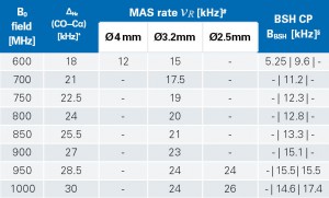
The BSH CP approach is dependent on moderate MAS rates (≤ 26 kHz) and high external magnetic B0 fields (≥ 600 MHz), since band-selectivity only works if the isotropic chemical shift difference between CO and Cα (Δ) considerably exceeds the MAS rate νR:

Usually, the average CO and Cα resonances appear at approximately 174 ppm and 54 ppm, respectively, resulting in a chemical shift difference (Δppm) of 120 ppm. For the conversion from ppm into Hz (ΔHz) the 13C gyromagnetic ratio γC and the external magnetic field Bo have to be taken into account:

For example, on a 600 MHz spectrometer the chemical shift difference of 120 ppm on 13C equals approximately 18 kHz:
ΔHz = 120ppm ×0.25×600MHz = 18000 Hz
Revisiting Equation (1) shows that only MAS rates below 18 kHz are applicable for the use of BSH CP experiments:
ΔHz = 18 kHz > νR
Before starting any BSH CP experiment, the external magnetic field B0 as well as the rotor size and the resulting MAS rate should be considered carefully. A detailed overview of suitable experimental settings is summarized in Table 1.
Parameter Optimization
Once these experimental conditions have been chosen, certain parameters need to be optimized: 90° hard pulses for 1H, 13C, and 15N, HC CP, HN CP, 1H high power decoupling, NCα double CP, NCO double CP, CαN double CP, 1H CW decoupling, and the different offset frequencies (center of CO/ Cα/ Call/ CαCβ resonances). Here, the use of Bruker’s TopSolidsbio leads to fast results.
Finally, the BSH CP specific parameters (CP contact time and power level, first and second trim pulse lengths where necessary, see Table 2 for detailed information) need to be optimized – ideally in their 1D ppg versions.
The provided Bruker pulse programs comprise detailed information about well-chosen parameter settings. Furthermore, Bruker offers a script called ‘calcbshcp’ that is calculating all relevant BSH CP parameters based on the chosen experimental conditions automatically. Nevertheless, a theoretical overview and formulae for manual parameter setting are presented in the following paragraphs.
How to Achieve CO – Cα Band-Selective CP Transfer
For cross polarization between two different nuclei, the Hartmann-Hahn (HH) condition needs to be fulfilled. Nothing less holds true for the homonuclear BSH CP:

Both, zero-quantum (ZQ, n = 1) and double-quantum (DQ, n = 2) homonuclear recoupling can be achieved when the sum or difference of the effective field strengths (Beff) acting on CO and Cα is equal to once or twice the MAS rate (νR). Experimental data have shown that DQ provides higher transfer efficiency compared to ZQ transfer. [5, 6]
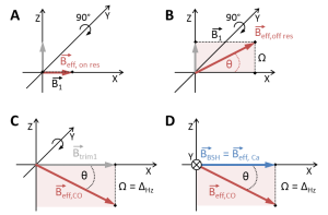
The effective field (Beff,x) for a spin X is determined by the applied RF irradiation field (B1) and the chemical shift offset (Ω) from the carrier frequency (known as the offset ‘o1’ in TopSpin, Figure 4A, B):

The 13C ΔHz of CO and Cα is known from Equation (2). Hence, if the carrier frequency is set on either of the two resonance bands (CO or Cα) during the BSH CP transfer, the chemical shift difference equals the offset:
Ω = Δ Hz .
Experimental results have shown that the Cα resonance band is not very dependent on the resonance position, while the CO chemical shift dispersion affects the effective field much stronger and can rapidly lead to a mismatch of the BSH CP condition.[5] Thus, the carrier frequency for RF irradiation should always be set on resonance in the middle of the Cα band (Figure 4A, D) resulting in an effective Cα field (Beff,Cα that equals the applied B1 field:
Beff,Cα = B1 .
With the knowledge of the chemical shift offset and the MAS rate, the RF field strength B1 to allow for BSH CP transfer (= ‘BBSH’ in the following) between CO and Cα can be calculated. When choosing the favored DQ transfer, the HH condition (Equation (3)) results in:
2×vR = Beff,CO +Beff,Cα. (3)
Considering Equation (5) Equation (3) can be solved for Beff,CO:
Beff,CO = 2×vR −BBSH. (3)
Equation (3) can be equated to Equation (4):
2×vR –BSH = BSH2+ΔHz2)1⁄2 (3=4)
and solved for BBSH, the field strength needed for the BSH CP condition:
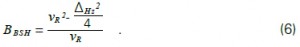
Revisiting the example of the previous page, we know that ΔHz is 18 kHz. When spinning at e.g. 15 kHz, the BSH CP spin-lock pulse, which fulfills the HH condition, becomes:
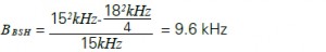
The last column in Table 1 summarizes the effective B1 fields for the suggested experimental conditions.
CO Trim Pulse for CO-Cα BSH CP
In BSH CP sequences with a polarization transfer from Cα to CO, CO magnetization is aligned along Z before the BSH CP. Because of the chemical shift offset from CO to Cα, the RF irradiation field (BBSH), which is on resonance with Cα, flips CO magnetization directly into the needed Beff,CO direction (XZ-plane, light red) to fulfill the HH condition (compare Figure 4B and D).
On the other hand, in BSH CP sequences with a polarization transfer from CO to Cα, Cα magnetization is aligned along Z, while CO magnetization is oriented along X after the specific NCO CP (Figure 2, dark blue). Thus, by applying BBSH along X, the effective field of CO would not be flipped into the needed direction for CP transfer, but stay along X.
Therefore, a trim pulse has to precede the BSH CP to flip CO magnetization into the effective off resonance CO field (Beff,CO) of BBSH (Figure 2 and Figure 4C, D). This can be done by applying a hard trim pulse on resonance with the CO resonance band (red-filled pulse in Figure 2C, known as ‘p28’ in Bruker pulse programs).
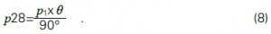
The required flip angle θ is calculated by:
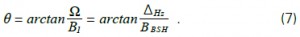
In our example, the flip angle is:
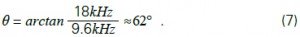
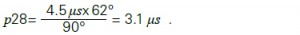
Usually, the flip angle θ is about 62-63°. With respect to the 13C 90° pulse length (‘p1’ in Bruker pulse programs), p28 is calculated as:
Assuming that the 13C 90° pulse has a strength of 55.6 kHz (corresponding to a pulse length of 4.5 μs) a 62° flip pulse would need a length of:
Trim Pulse for CO Detection
A further trim pulse has to be applied whenever CO signal shall be detected, e.g. in the hNCαCO, but also in a 2D hNCOCα (Figure 2, red-framed pulse, known as ‘p29’ in Bruker pulse programs). In any other experiment, where CO is already detected in an indirect dimension (as e.g. in the 3D hNCOCα version) no second trim pulse is needed, since it would only maximize diagonal CO-CO peaks, but no CO-Cα cross correlation peaks.[5-7] As is described in the relevant ppg, the trim pulse can be activated for the different dimensions by setting the flag ‘-Dflip’ in the ‘zgoptns’.
Figure 5 depicts the location of effective fields (A) and magnetization(B) during a BSH CP. While Cα magnetization (MCα,BSH) is spin-locked along X, CO magnetization (MCO,BSH, corresponding to Beff,CO) is located in the XZ-plane (light red), but needs to be flipped into XY for detection.
To further spin-lock the Cα magnetization for detection as well, this second trim pulse (Btrim2 can only be applied along X. Under these conditions the maximum remaining CO magnetization can only be detected, when it is aligned exactly on the Y axis (resulting in a 90° phase shift of CO signal compared to Cα signal).
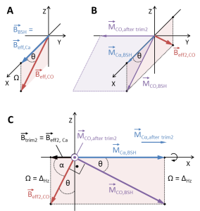
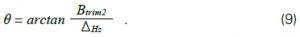
As can be seen in Figure 5B, after the BSH CP the MCO,BSH is perpendicular to the Y axis (purple plane). Hence, to flip the CO magnetization onto the Y axis (MCO,after trim2), only a trim pulse along X is permitted that creates an effective field Beff2,CO), which is perpendicular to both, MCO,after trim2 and MCO,BSH. Figure 5C shows, that Btrim2 must be applied along -X to produce this Beff2,CO. The angle between MCO,BSH and the X axis equals the angle between Beff2,CO and the Z axis (θ).
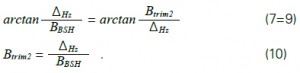
As in Equation (7) θ can be expressed as:
When equating Equations (7) and (9), we can solve for the missing field strength of the second trim pulse:
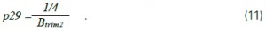
The calculated amplitude of Btrim2 needs to be converted into the length of a 90° pulse, because the effective Beff2,CO field is shifted by 90° from MCO,BSH. Finally p29 becomes:
For our example this would mean a Btrim2 field and a length p29 of:
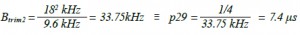
Finally, when applying the RF field strength BBSH for 7.4 μs, the CO magnetization becomes detectable in our example.
References
- N.M. Szeverenyi et al. Observation of spin exchange by two-dimensional fourier transform 13C cross polarization-magic-angle spinning. J Magn Reson (1982) 47:462-475.
- A.G. Pines et al. Proton-enhanced NMR of dilute spins in solids. J Chem Phys (1973) 59:22.
- K. Takegoshi et al. 13C-1H dipolar-assisted rotational resonance in magic-angle spinning NMR. Chem Phys Lett (2001) 344:631-637.
- M. Baldus et al. Cross polarization in the tilted frame: assignment and spectral simplification in heteronuclear spin systems. Mol Phys (1998) 95:1197-1207.
- V. Chevelkov et al. Efficient CO–CA transfer in highly deuterated proteins by band-selective homonuclear cross-polarization, J Magn Reson (2013) 230:205–211.
- V. Chevelkov et al. Efficient band-selective homonuclear CO–CA cross- polarization in protonated proteins, J Biomol NMR (2013) 56:303–311.
- C. Shi et al. BSH-CP based 3D solid-state NMR experiments for protein resonance assignment, J Biomol NMR (2014) Epub ahead of print.
- R. Verel et al. A homonuclear spin-pair filter for solid-state NMR based on adiabatic-passage techniques. Chem Phys Lett (1998) 287:421-428.