Generating a Stribeck Curve in a Reciprocating Test
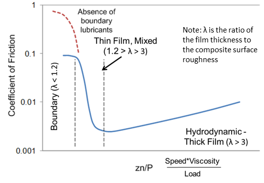
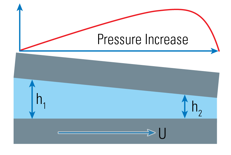
The term Stribeck curve is used to describe a plot showing the frictional characteristics of a liquid lubricant over conditions usually spanning the Boundary, Mixed and Hydrodynamic regimes. Each regime is defined by the ratio of the film thickness to the surface roughness, or the λ ratio (Figure 1). Such curves are often used to evaluate the effect of changes to the lubricant’s viscosity or to the lubricant’s additive package, or the effect of surface roughness. The primary requirement for generating a Stribeck curve is a fluid that can be drawn into a converging gap, thus creating a pressure increase to support the load (Figure 2).
Historical/Traditional Test Geometry
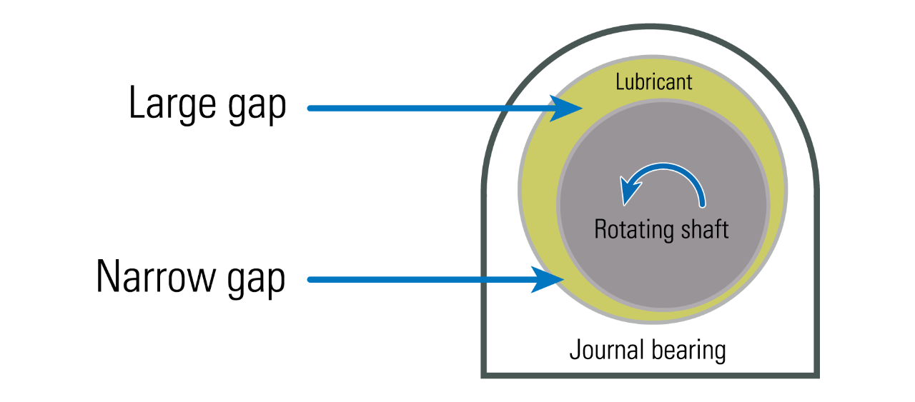
The classic work of Thurston1, Martens2, Stribeck3 and Hersey4 were done using a journal-bearing geometry, which possesses all of the above requirements (Figure 3). An instrumented journal-bearing test allows for evaluation of the friction over a range of relative velocities and/or loads. In a Stribeck curve the key parameter, against which the coefficient of friction (COF) is plotted, is called the Hersey number. The Hersey number is the dimensionless number obtained from the velocity (m/s) times the dynamic viscosity (Pa∙s = N∙s/m2), divided by the load per unit length of bearing (N/m).
The simplest method to obtain a Stribeck curve and the method most commonly used, provided one has the appropriate converging gap geometry, is to keep two variables fixed (e.g., load and viscosity) and vary the third (e.g., velocity) over a suitable range so that the contact interface goes through the region of asperity contact (boundary), as well as full fluid-film separation (hydrodynamic). In the laboratory this is most easily done in a unidirectional manner using a pin-on-side against a rotating disk (POD) under flooded lubrication, with the pin-end contact geometry creating the converging gap.
Reciprocating Motion for Stribeck Curve Generation
Recently, however, there has been considerable interest in evaluating lubricant frictional characteristics using a reciprocating test mode. Such test rigs are sometimes referred to as a high-frequency reciprocating rig (HFRR) or SRV-type test. (SRV is an acronym for the German expression Schwingung Reibung Verschleiß, which meansreciprocating friction and wear). An example of how a reciprocating test mode might be used is to simulate the lubrication condition of a piston ring in a cylinder in an automobile engine.

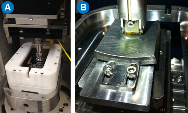
The challenge for developing a Stribeck curve in the reciprocating mode is to develop enough velocity, over a long enough stroke length before reversal, to build up the pressure and film thickness required to reach the hydrodynamic lubrication regime. This note describes such a test using the geometry of a polished cylindrical dowel pin- on-side against a highly polished flat plate, under conditions of high-frequency reciprocating motion. A Bruker UMT TriboLab (Figure 4), equipped with a heated high-speed reciprocating stage, was set up for this work.
In such a high-frequency reciprocating rig (HFRR), the 30 Hz conditions give an average velocity of 0.42 m/sec and a maximum at mid-stroke of 0.59 m/sec, high enough to reach the hydrodynamic lubrication regime. A standard cylindrical steel dowel pin (9.5 mm diameter x 15.5 mm long, roughness 19 µm Ra) was held in a pivoting self-aligning holder and loaded against a highly polished 52100 steel plate (0.013 µm Ra). Figure 5a shows the samples in the test chamber. As an alternative to the cylindrical pin-on-side and a flat plate, samples fabricated from actual components also can be used (Figure 5b).
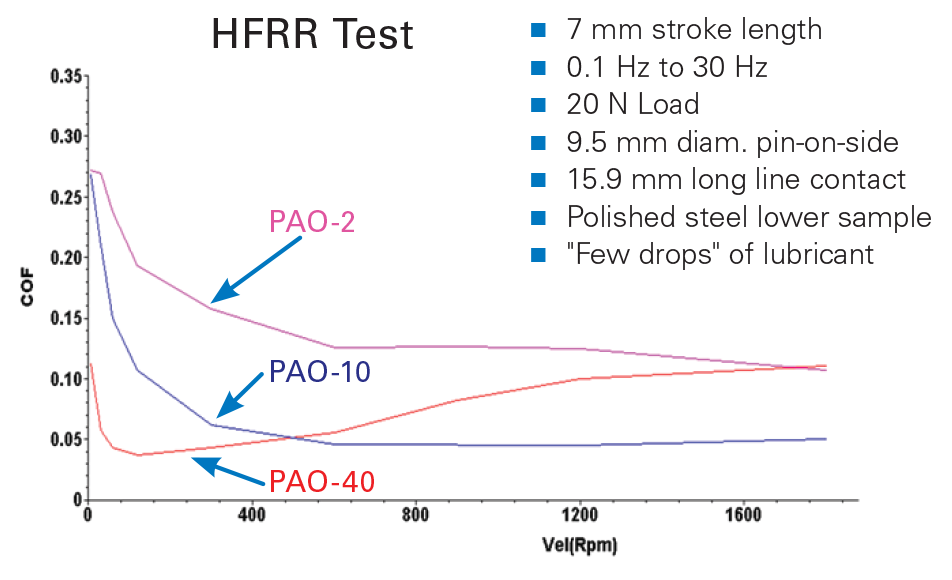
The stroke length was fixed at 7 mm and the load at 20 N for all tests, and the frequency was varied from 0.1 Hz up to 30 Hz. Three different viscosity poly-alpha olephin oils (PAOs) were used, namely PAO-2, PAO-10 and PAO-40 (the dash number refers to the viscosity in cSt at 100°C). Tests were conducted at room temperature. Figure 6 shows the resulting Stribeck curves from tests of these three viscosity lubricants.
Additional Standard Reciprocating Test Capabilities
While there is currently no standard published test method for generating a Stribeck curve, either in reciprocating or unidirectional motion, a number of other lubricant performance-related tests can be conducted with the same reciprocating motion for the lower sample. By exchanging the cylinder-on-side upper sample for either a ball or a flat-pin, and adjusting the frequency and/or stroke-length, the same setup can be used to run the following standard ASTM-, DIN- or ISO-issued reciprocating tests:
ASTM D5706-11: Standard test method for determining extreme pressure properties of lubricating greases using a high-frequency, linear-oscillation (SRV) test machine
ASTM D5707-11: Standard test method for measuring friction and wear properties of lubricating grease using a high-frequency, linear-oscillation (SRV) test machine
ASTM D6425: Standard test method for measuring friction and wear properties of extreme pressure lubricating oil
ASTM D6079-11: Standard test method for evaluating lubricity of diesel fuels by the high-frequency reciprocating rig (HFRR)
ASTM D7688-11: Standard test method for evaluating lubricity of diesel fuels by the high-frequency reciprocating rig (HFRR) by visual observation
ASTM D7594-11: Standard test method for determining fretting wear resistance of lubricating greases under high Hertzian contact pressures using a high-frequency, linear- oscillation (SRV) test machine
ASTM D7755-11: Standard practice for determining the wear volume on standard test pieces used by high- frequency, linear-oscillation (SRV) test machine
ASTM G133-10: Standard test method for linearly reciprocating ball-on flat sliding wear
ASTM G203-10: Standard guide for determining friction energy dissipation in reciprocating tribosystems
ASTM G206-11: Standard guide for measuring the wear volumes of piston ring segments run against flat coupons in reciprocating wear tests
DIN 51834: Determination of friction and wear data of lubricating oils
ISO 12156-1:2006: Diesel fuel — assessment of lubricity using the high-frequency reciprocating rig (HFRR), Part 1: Test
Author
Steve Shaffer, Ph.D.
Bruker Senior Applications Scientist
References
- Thurston, Robert H., Determination of the Laws and Co-efficient of Friction by New Methods and with New Apparatus, Trübner and Co, London, 1879.
- Martens, Adolf, Schmieröluntersuchungen [oil studies], Mitteilungen aus den Königlichen Technischen Versuchsanstalten zu Berlin, Ergänzungsheft III [releases from the Royal Technical Testing Institutes of Berlin, complementary volume III], Julius Springer, Berlin, 1888, 1–37.
- Stribeck, Richard, Die Wesentlichen Eigenschaften der Gleit- und Rollenlager [the main characteristics of the sliding and roller bearings], Zeitschrift des Vereins Deutscher Ingenieure [Journal of the Association of German Engineers] 36 (Band 46), 1902, 1341– 48,1432– 38, and 1463 –70.
- Hersey, Mayo, The Laws of Lubrication of Horizontal Journal Bearings, Journal of the Washington Academy of Sciences, 4, 1914.
- Society of Tribologists and Lubrication Engineers — www.stle.org
