DIFFRAC.TEXTURE
All-round Texture Analysis Meets Ease-of-Use
Materials and components properties are significantly influenced by an inherent or applied preferred orientation, or texture, which can be non-destructively investigated by X-ray diffraction methods.
DIFFRAC.TEXTURE is the powerful and easy-to-use software suite designed to analyze texture measurements. By utilizing a systematic approach to analysis according to a flowchart, DIFFRAC.TEXTURE delivers comprehensive texture information with just a few mouse-clicks.
DIFFRAC.TEXTURE features two well established and complementary techniques to provide the most accurate and reliable results: the model independent Spherical Harmonics methods and the model dependent Component Method.
With the implementation of the latter in DIFFRAC.TEXTURE, all crystal systems are now supported and the variety of sample symmetries ensures that a huge diversity of textures can be handled.
- Straightforward creation of pole figures from 0D, 1D and 2D measurement data with single-click assignment to crystal phases.
- Spherical Harmonics method for direct computation of the Orientation Distribution Function.
- Component method for fully detailed model based texture analysis.
- Ellipse component for the flexible modeling of anisotropic textures.
- Comprehensive, extensible Material Database.
- Powerful texture representation capabilities and extensive report generator.
Texture analysis workflow
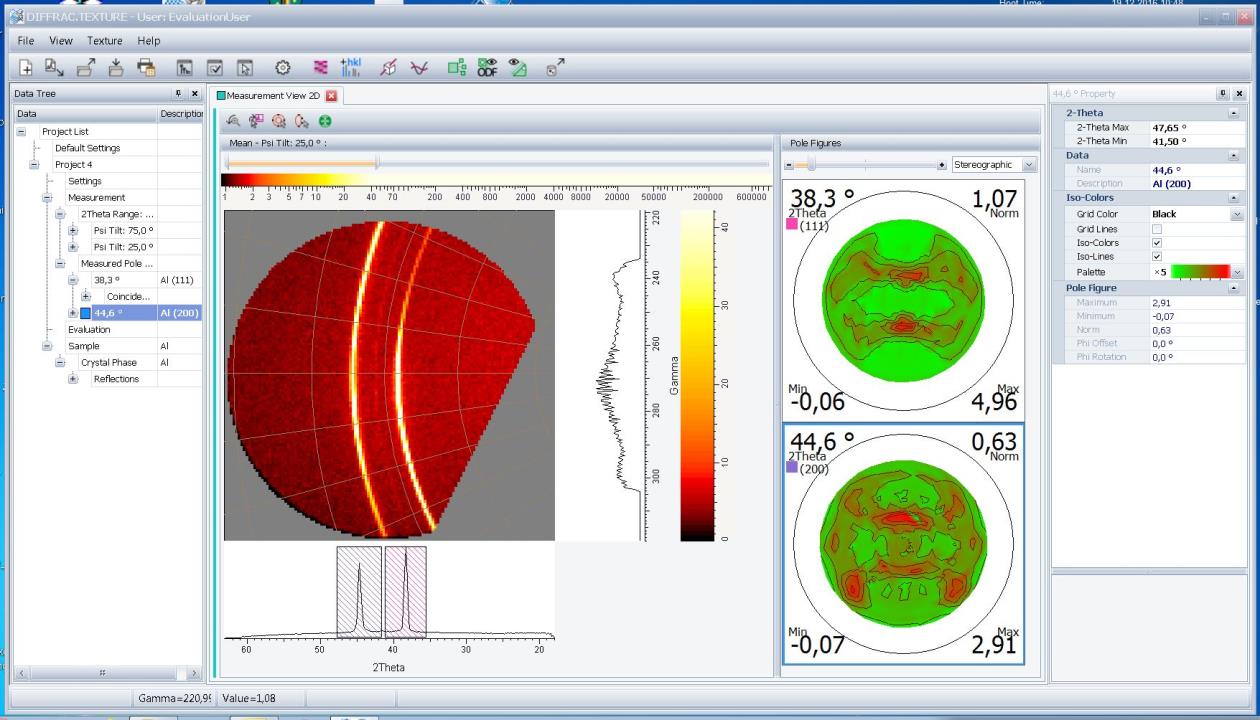
1. Data import and pole figure generation
The generation of pole figures from measured data has never been easier.
DIFFRAC.TEXTURE can import 0D, 1D or 2D data and instantly create pole figures with single click operation either from selected angular regions or directly from 2D frames.
2. Linking texture model and pole figures
DIFFRAC.TEXTURE comes with a comprehensive crystal structure database that allows linking of pole figures to the corresponding hkl reflections with the least little effort. Overlapping signals from different phases can be easily assigned to facilitate data analysis.
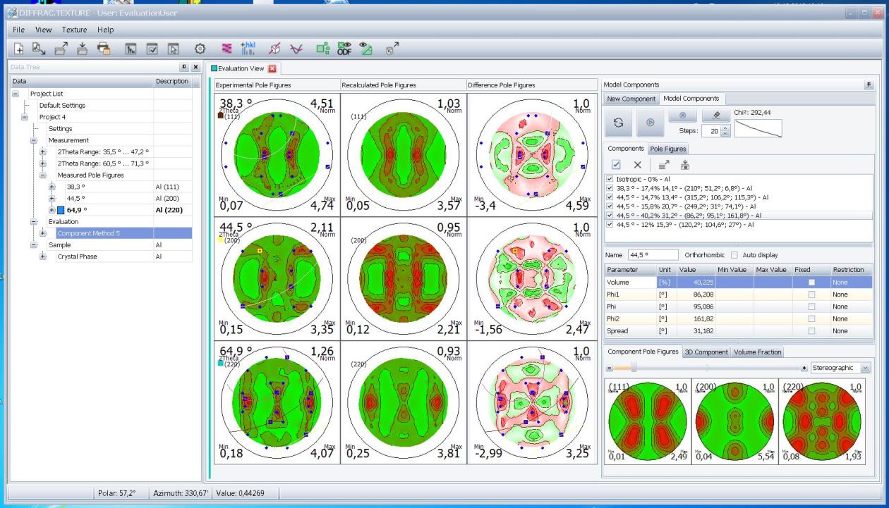
3. Pole figure analysis
DIFFRAC.TEXTURE features two complementary and powerful analysis methods that deliver accurate and reliable results:
- The model-independent Spherical Harmonics method directly calculates the Orientation Distribution Function (ODF) from pole figures with a single mouse-click.
- The Component method is a model-based approach that fits a set of texture components to the pole figures using fast and robust least-squares optimization.
With the ODF at hand and the ability to model the process symmetry of texture components, DIFFRAC.TEXTURE provides a self-consistent and comprehensive picture of the texture.
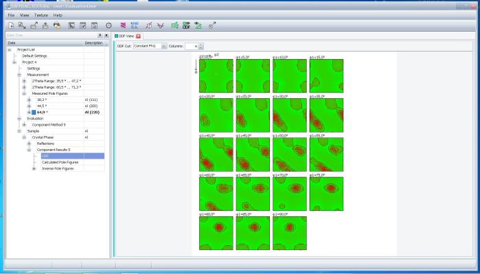
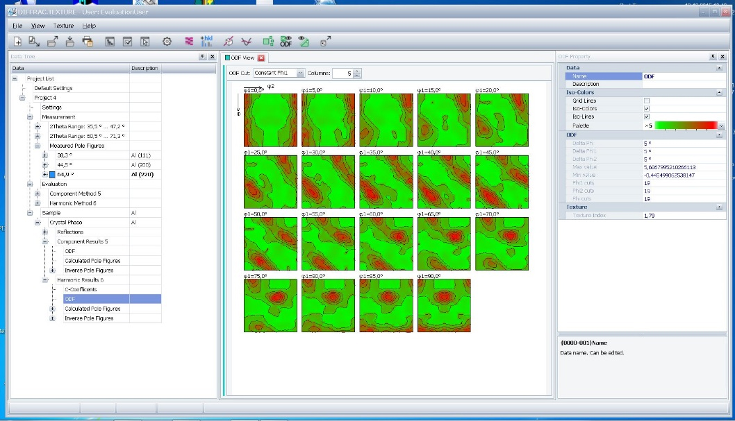
4. Texture representation
DIFFRAC.TEXTURE includes powerful tools and options for a more detailed analysis of the obtained textures:
- ODFs represented in 3D or as a set of 2D sections.
- Calculated pole figures allow visualization of the complete pole figure to better understand the sample’s texture.
- Inverse pole figures along the surface normal, in-plane rolling and transverse directions give clues to the origin of a components texture.
- 3D visualization of the individual texture components to support a better understanding of their orientation.
- Pie-chart representation of the components’ volume fractions, including the isotropic content.
Two approaches to texture analysis
Spherical Harmonics method
The Spherical Harmonics method is a model-free approach and the method of choice if the orientation distribution function is of primary interest. The ODF is directly calculated from a series expansion of the measured pole figures using a set of special functions defined on the surface of a sphere – the generalized spherical harmonics.
The advantage of the method is that it provides texture results in the form of the ODF in a fast and simple way without requiring prior sample knowledge.
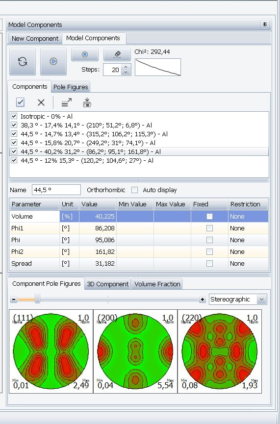
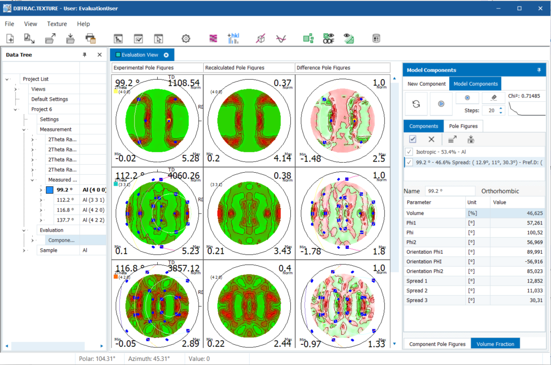
Component method
The Component method is a model-based approach: The texture is modelled by a set of components that describe the orientation, crystal and process symmetry of a part of the sample. From these texture components the corresponding pole figures are calculated. The parameters of the components are then refined by fitting the simulated pole figures against the measured ones using robust least-squares optimization. Unlike the Spherical Harmonics method which uses mathematical functions to model the texture, the Component method provides a direct connection to the material‘s physical structure providing a deeper insight into the process symmetry of the sample. Texture components provide a direct link between the manufacturing and processing of the sample and the measured pole figures and overall ODF.
No reason to choose, both methods are only a few clicks away!
A typical analysis may begin with a quick fit with Spherical Harmonics to provide insights into the texture. Armed with this information, further fittng using the Component Method yields quantitative results directly connected to the physical structure of the material.
In the case of materials which exhibit broad textures, such as rolled metal sheets, Spherical Harmonics followed by inspection of the inverse pole figures is all that is needed. On the other hand for samples with strong preferred orientations, a full description of the texture can be achieved by using very few texture components. One important field is thin film research where pronounced textures occur. Here the Component method is the preferred analysis technique as it provides the quantitative direction and degree of orientation of both.
Ellipse component — Bridging the gap
The Ellipse component bridges the gap between the spherical component (isotropic orientaton spread) and the fiber component (fiber axis with orientation spread).
The ellipse‘s additional degrees of freedom (shape & orientation) allow the description of anisotropic textures that have been difficult to model up to now.
Maximimun flexibility
An ellipse component is defined by:
- preferred Orientation of the component given by the Euler-Bunge Notation: (ϕ1, Φ,φ2).
- Orientation of the Ellipsoid relative to the preferred orientation.
- Spread (Spread1, Spread 2, Spread 3) of the rotated ellipsoid.
Highly anisotrophic textures and preferred orientations typically occur due to mechanical treatment. Ellipse componens not only simplify modelling of these samples by reducing the number of components, but also provide a more direct connection to the process!
DIFFRAC.TEXTURE Resources
Flyers & Application Notes & Reports
Keep your DIFFRAC.TEXTURE up to date
Free Maintenance Update
The free DIFFRAC.TEXTURE Maintenance Update renews your TEXTURE version to the most recent release. Regardless of your TEXTURE license level, you can always download the latest Maintenance Update from www.brukersupport.com, free of charge!
Download process
- Register at Bruker Customer Support
- Click on the "Software" button
- Search for the DIFFRAC.TEXTURE Maintenance Update
- Download the update
Bugfixes
By keeping your DIFFRAC.TEXTURE up to date, you will benefit from all bugfixes made for the current but also all previously released versions, regardless of the license level. DIFFRAC.TEXTURE Maintenance Updates are cumulative and can therefore be applied to any previous version.
What are Upgrades?
DIFFRAC.TEXTURE Maintenance Updates do not come with new features. If you want to benefit from features introduced in new major releases you need to purchase the latest DIFFRAC.TEXTURE upgrade.