SENTERRA II
常時校正
最高の精度
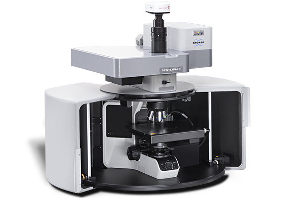
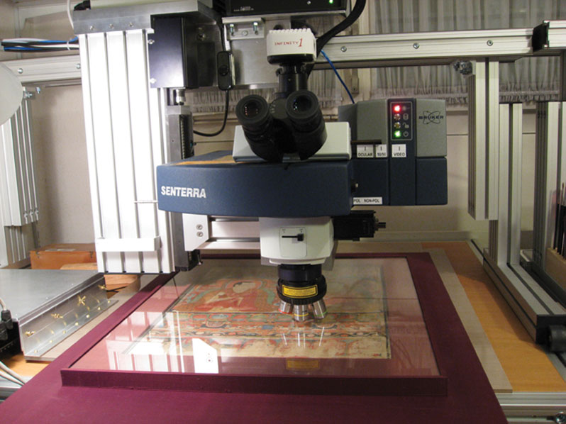
顕微 ラマン のパートナー: SENTERRA II
正しいラマン顕微鏡の秘訣
自動化は SENTERRA II の重要な機能です。これにより、ユーザーは本質的なことに集中できます。分析における課題、ラマン測定、そして何よりも重要なのは、その結果です。
SENTERRA II 技術的特長:
- 完全に自動化されたハードウェア
- 最大 4 つのレーザーをワンクリックで切り替え
- SureCal™ 連続自動波数校正機能
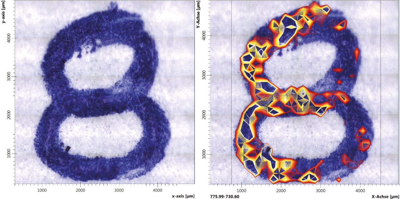
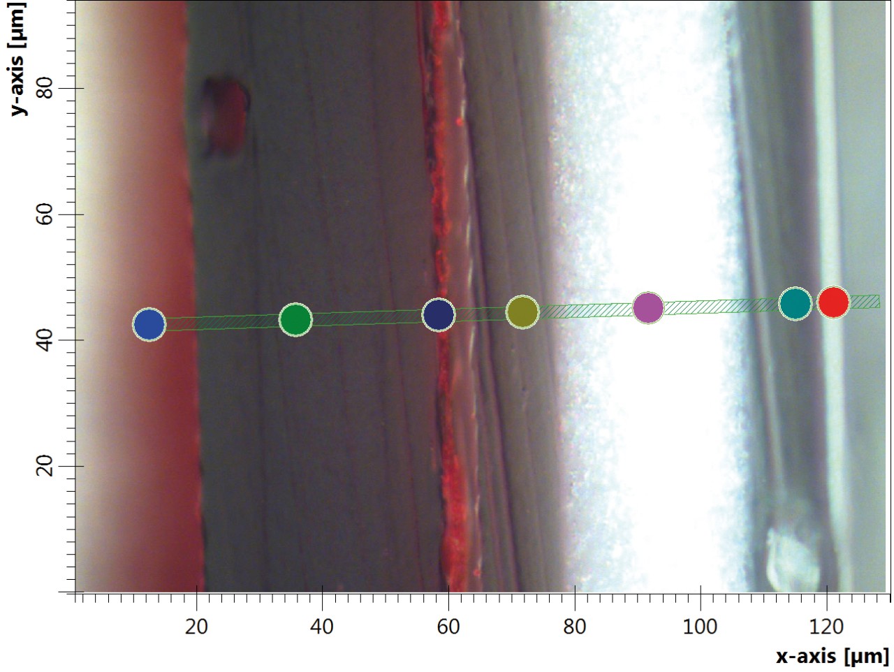
- 高速3Dラマンイメージング
- 独自のワークフローを自動化
- 強力な分析および識別ツール
- フーリエ変換ラマン (FT-Raman) による蛍光抑制
- FT-IR との組み合わせ
- 画面表示に従うだけの簡単操作
- リサーチグレードの分光性能
- 優れた波数精度
- 自己診断と自動化された OQ / PQ テスト
- 実質的にメンテナンスフリーの操作
- GMP、21CFR part 11 完全準拠
SENTERRA IIアプリケーション:
- 医薬品
- 材料科学
- 高分子・プラスチック
- 環境分析
- 法医学
顕微 ラマンにおけるデータの再現性、精度、ユーザーセーフティ
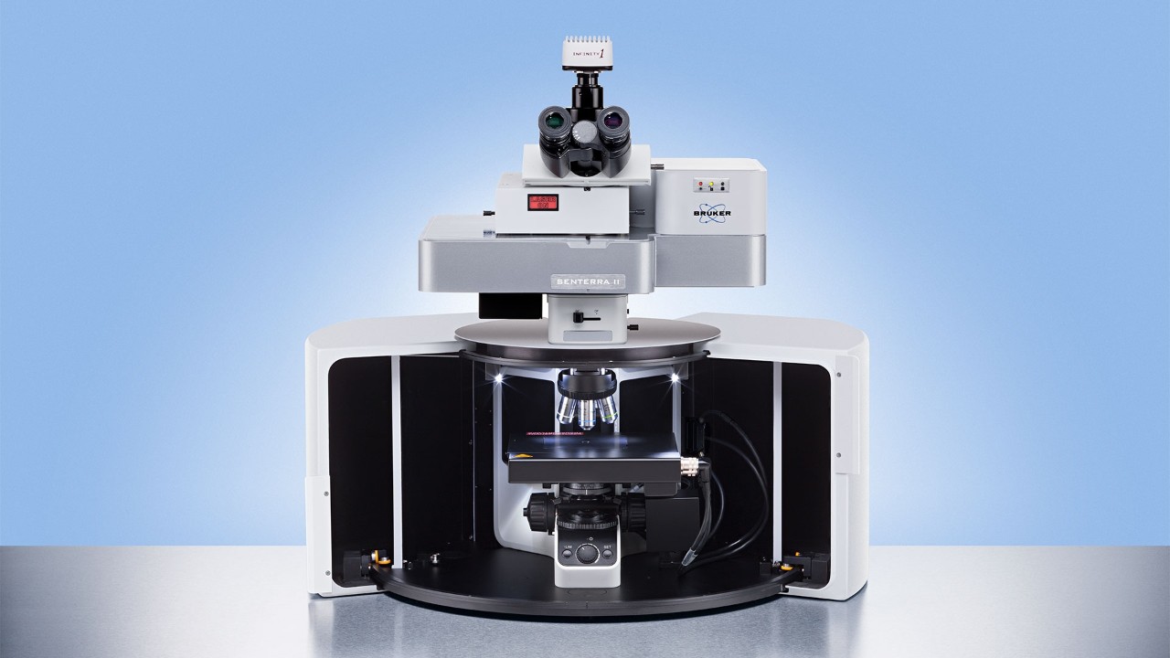
1. SENTERRA II は、自己診断やOQやPQなどの機器テストを含めて完全に自動化されています。マウスをクリックして必要なレーザーを選択するだけで、フィルターやグレーティングの切り替えと調整も自動的に実行されます。
2. SENTERRA II の自動制御機能による利便性を最大限にするために、独自の特許技術による連続波数校正機能 SureCal™を完成させました。この機能はシステムを連続的に再校正し、再現性に優れる波数値を永続的に維持します。
3. 測定に不慣れなオペレータにとって重要な要素のひとつに安全性があります。レーザー製品の安全基準クラス 1 に準拠するハウジングとインターロックを装備する SENTERRA II は、有害なレーザー放射からオペレータを常に保護します。
SureCal 連続自動ラマン校正
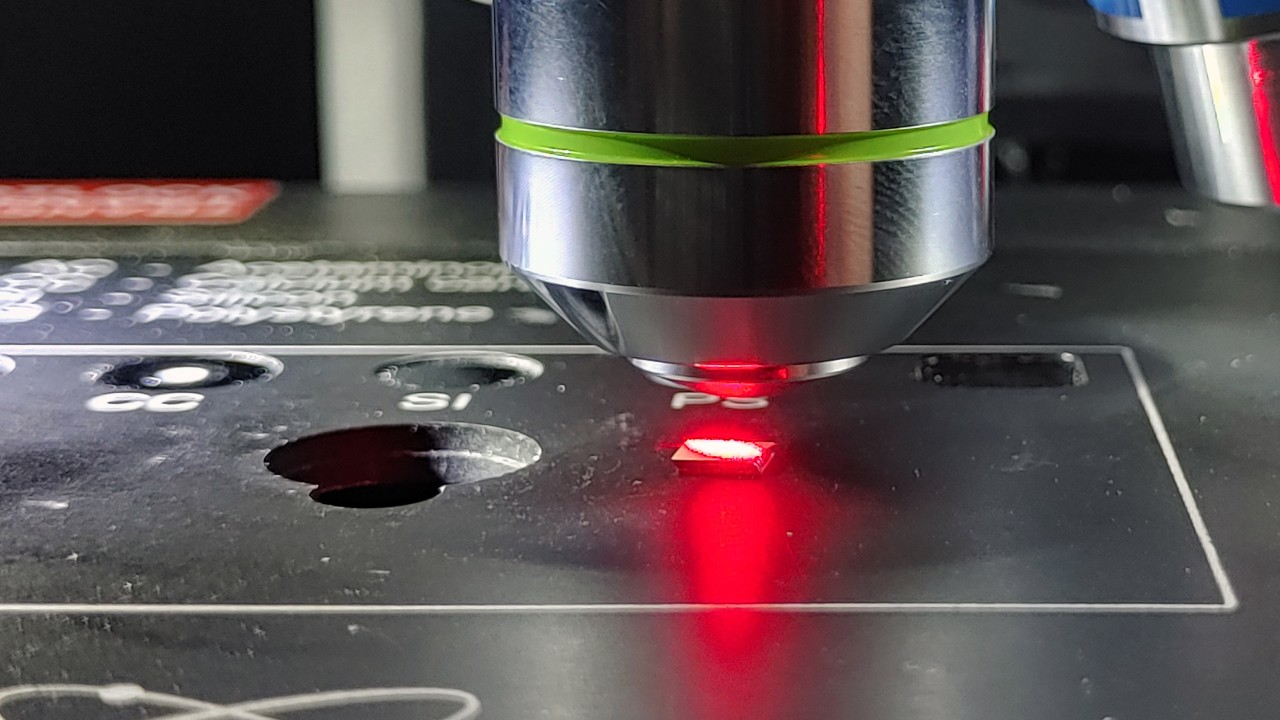
当然のことながら、SENTERRA II は変わることのない高いスペクトルおよびラマンイメージング性能を優れた感度とともに提供します。しかし、この共焦点ラマン顕微鏡の真の実力は、SureCal™テクノロジーにあります。
測定環境の変動、特に温度変化や振動は、顕微ラマンシステムの光学系および機械系に影響を与え、結果としてラマンシフト (波数) の変異を引き起こします。この変動を常に補正して、より正確な波数値が得られるようにすることが、ラマン測定において最も重要な原理的要素のひとつです。
SureCal™機能により、SENTERRA II は波数が常に校正されている唯一のラマン顕微鏡です。煩わしい波数の再校正は装置に任せて、貴重な時間はすべて分析に使いましょう。簡単な材料識別であろうと、PCA などの統計的手法が求められる大量のデータセットの測定であろうと。
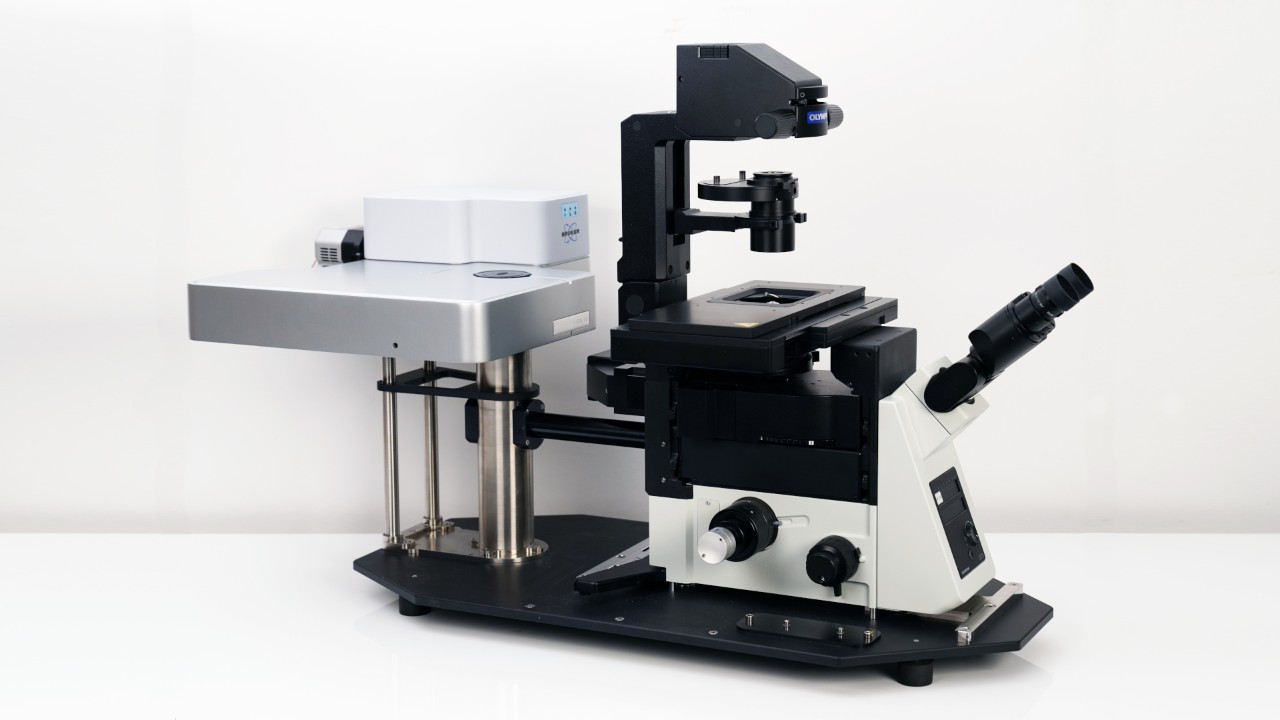
ライフサイエンス分野への応用
SENTERRA IIは、機能性を損なうことなく倒立顕微鏡を搭載することも可能です。倒立型ラマン顕微鏡は、オープンアクセスな設計でサンプルリングを行いやすく、特に組織や細胞の特性評価に適しています。さらには、in vitroでの医薬品の検証やin situでのラマン測定など、顕微鏡ステージへのより良いアクセスが必要とされる研究にも、アドバンテージをもたらしてくれます。
すべての研究者に
あらゆる種類のアプリケーションに使える強力なラマン顕微鏡プラットフォーム、それが SENTERRA II です。高度に自動化された各種機能、コンパクトなボディ、効率的な操作性など、SENTERRA II は、研究開発のみならず、品質管理用途などのルーチンワークにおいても頼りになるシステムです。
顕微ラマンのアプリケーションを選択してください
芸術品の保存修復
法医学
医薬品
高分子とプラスチック
材料科学
環境分析

SENTERRA II アプリケーションビデオ
OPUS 8.7 | SENTERRA II | 2021年Q3リリース情報
新機能:OPUSにPythonスクリプトインターフェイスを実装
OPUS 8.7では、OPUS内の新しいPython環境により、カスタマイズされたデータ処理・解析方法をより簡単に利用できるようになりました。データに対して特別なアルゴリズムを必要とするユーザーに門戸を開くものです。Pythonスクリプトは、ラマン測定直後にOPUSで実行することができます。後処理を本当に自分のものにし、Pythonで日常的な測定にもたらすすべての力を楽しんでください。
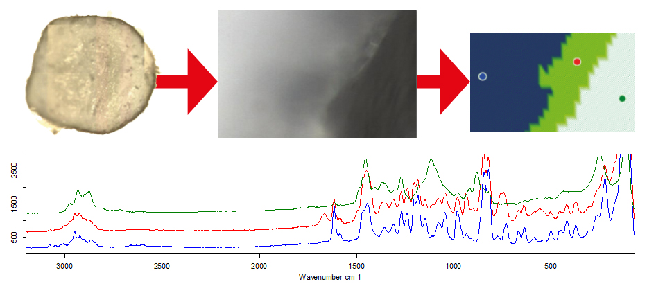
新機能:適応的K平均クラスタリング機能による高性能ケミカルイメージング生成法
新しいラマンデータ解析機能:適応的K平均クラスタリングをリリースしました。これは、ビルドインのPython環境を利用して作成されました。この新機能により、特定のラマンピークを選択する必要が全くなく、測定後に直接ケミカルイメージングを生成することができます。スペクトルを自動的にグループ分けし、ラマンイメージを自動的に生成してくれます。既知のサンプルを使用するアプリケーション、例えば複数の主薬を含む医薬品の錠剤などでは、この機能によりユーザーにラマンイメージをすぐに提供でき、時間を大幅に短縮することができます。また、未知試料の実験では、自動ラマンイメージングにより、試料が均質であるか、化学的な構造を持つかどうかを一目で判断することができます。
SENTERRA IIで利用できるその他の新機能:
- 3Dスペクトルデータからクラスを識別する”クラスターID”機能
- 新たな粒子検出法が追加された「パーティクルファインド(粒子検出)」機能
- SENTERRA IIのOVPが新しいOVP-Xに対応

資料ダウンロード
当社のラマン顕微鏡とソリューションの詳細については、こちらから資料をご確認頂けます。


