Tech Note: Tip-Enhanced Raman Scattering (TERS) combining JPK NanoWizard® AFM with a Raman System
The combination of Raman spectroscopy with AFM empowers the correlation of the information gathered by both techniques simultaneously. Conventional Raman spectroscopy with AFM enables the acquisition of chemical information in conjunction with the surface topography. To perform analysis with highest spatial resolution in the nanometer range, TERS integrates the Raman-enhancing benefits of the SERS-effect and the accuracy of the closed loop positioning of Bruker's NanoWizard AFM.
With this easy-to-operate setup, users can achieve hassle free high spatial resolution Raman information. By the modular and flexible design of the Bruker setup, it is easy to upgrade any existing Raman spectrometer. Implementing automated communication, a user-friendly data acquisition is enabled, bringing the sensitivity and spatial resolution of Raman measurement to a next generation level.
KEYWORDS: Atomic Force Microscopy; AFM; NanoWizard, Tip-Enhanced Raman Scattering; TERS; TAO module; Optical Integration
Readers can expect to learn about:
- How Bruker's dedicated design criteria and accessories of the NanoWizard AFM such as the TAO module enable the perfect combination of TERS and AFM;
- Instrumentation and detailed steps of the system configuration, including application examples outlining the seamless integration of the NanoWizard AFM into commercially available Raman spectroscopes; and
- The benefits and the potential of the NanoWizard AFM when combined with an inverted Raman microscope for simultaneous investigations of topographical and chemical sample properties;

Introduction
The combination of Raman spectroscopy with AFM empowers the correlation of the information of both techniques simultaneously. Conventional Raman spectroscopy together with AFM enables chemical information in conjunction with the surface topography. But this kind of Raman mapping has several drawbacks. On the one hand the intrinsic weak Raman signal and on the other hand the diffraction limited spatial resolution. In order to perform analysis with highest spatial resolution in nmrange, TERS1 integrates the Raman-enhancing benefits of the SERS-effect2 and the accuracy of the closed loop positioning of the NanoWizard® AFM.3 Here the metal coated AFM tip is used as a field enhancer while scanning over the surface. One will get Raman signals with the spatial resolution in the order of the tip diameter of the apex simultaneous to the surface information such as topography and phase, provided by the AFM.
JPK established in 2002 the first combination of a Raman spectrometer and a closed loop 5 axis AFM system for TERS experiments. This method was developed with leading experts from the near field optical and Raman community.

Setup requirements for TERS experiments
Raman spectrometer options
The set up itself consist of a commercial available Raman spectrometer and an inverted microscope. Hereby you are not limited to a specific manufacturer or product. Raman spectrometer from Horiba Jobin-Yvon, Princeton Instruments and Renishaw in combination with inverted microscopes from Nikon (TE or Ti line), Zeiss (Axiovert or AxioObserver line), Leica (DMI line) and Olympus (IX line) can easily be implemented setting up such a highthroughput turn-key TERS-system. Working in transmission mode the NanoWizard® AFM is placed on top of the inverted microscope.
Raman spectrometer systems ready for integration:
- Horiba Jobin Yvon: XploRa, iHR and LabRAM HR
- Renishaw: inVia
- Princeton Instruments: Acton Advanced

Stability and minimized drift of the AFM system
Key components for a successful TERS experiment are the AFM stability regarding drift and scanner performance. The NanoWizard® AFM is designed to reach highest AFM resolution on top of an inverted microscope in combination with the TAO™ sample scanning module and a coverslip based sample carrier. But not just highest resolution alone is crucial for TERS. Because of the long integration times of the optical detector in the Raman spectrometer (which is typically an EM-CCD) long term stability is the key parameter. It takes minutes to acquire a spectrum at a certain point of the sample. Therefore it is important to have a system with lowest drift. This is given by the symmetric design of the AFM head, stage and sample holder. The use of intelligent material combinations regarding drift also in context to the material of the optical microscope base makes the system stable over long time.
SEE THE LATEST GENERATION NANOWIZARD

5 or 6 axes closed loop scanners with the AFM/TAO™ combination
In order to prevent the movement of the optical pathway during imaging, an additional sample scanner (TAO™) is implemented into the system. Depending on which version, the Tip Assisted Optics (TAOTM) module enables the movement of the sample in XY or XYZ direction, respectively (Figure 1) with absolute stability leading to peak performance for this cutting-edge application. This makes the system to a 5 or 6 axis scanning setup with 3 axes in the head and additional 2 or 3 axes in the sample scanning stage. The TAO™ sample scanning unit is equipped with a high performance flexure scanner stage. This stage has extreme minimal bow and uses latest closed loop technology based on capacitive sensors. This ensures highest bandwidth combined with lowest position noise in closed loop feedback. With this additional sample scanner it is easy possible to perform highest resolution AFM measurements. Because of the design and the low noise electronics made by JPK the system adds no noise.
Optical alignment of the AFM tip to the optical focus
To produce a field enhancement effect with the AFM coated metal-tip - the tip must be positioned with absolute precision in the focus of the Raman excitation laser coming out of the high NA objective lens. Here it is important to find the maximum intensity. Thanks to the closed loop scanner and the JPK software the user can find the right position by scanning in the optical focus in a dedicated way. The signal is measured by an external photodetector. Maintained in this position, the tip induces a local electromagnetic field enhancement which can increase the Raman scattering signal dramatically.
TERS with highest NA on inverted microscope configuration
In TERS measurements the excitation laser is coupled into the inverted microscope and focused through a high numerical aperture objective towards the metal coated AFM tip. Due to the use of highest NA objective lenses it is essential to use coverslips with 170μm thickness. With JPKs coverslip based sample holders such as BioCellTM and CoverslipHolder it is possible to obtain the best results in optical experiments and highest resolution AFM in air or liquid. The reason here is that these holders are designed to give sub-nm stability even when an immersion objective lens are in contact with the coverslip and the sample is immersed in liquid. To archive this low noise level is not possible with other coverslip Fluidcells.

Optical cross-talk avoidance between AFM deflection system and Raman signal
To avoid interferences between Raman signal and internal AFM laser, all NanoWizard® AFM heads which are used for Raman related applications are therefore equipped with an internal laser using a wavelength of 980nm. Implemented in the AFM head one can find special optical filters to block the Raman excitation from the AFM detector.
LEARN MORE:
Advanced control electronics
The NanoWizard® head and the TAO™ module are driven by the new Vortis™ SPM control station. This is a digital controller with lowest noise and highest bandwidth. The DAC converter circle, closed loop sensor electronics together with the high voltage amplifiers are made with lowest noise level. This ensures that the flexure scanners are always in an exact position and free of jitter. The system comes with a huge number of user accessible analog and digital signal channels via the SAM front panel module, multiple fast lock-in amplifiers and high-end piezo drivers with closed-loop control. The user can choose a variety of feedback control options to drive different setups with tuning forks, STM based systems or one with high frequency cantilevers.
Synchronization between AFM and spectrometer
To acquire TERS data at a certain sample point the positioning of the AFM-tip must be controlled according the data acquisition time needed from the spectrometer. The communication and software synchronization between Raman spectrometer and AFM is established by user friendly scripting in the JPK software and allows semiautomatic dataacquisition.

AFM usability and operation modes
The NanoWizard® AFM platform in combination with the TAO™ module keeps all of the AFM operation modes available to the user. Imaging, force spectroscopy, force mapping, point spectroscopy, lithography or nanomanipulation experiments are possible without restrictions.
The system is designed for hassle-free work for experts as well as for newcomers. Robust hardware and the dedicated software make it straight forward to generate data. For advanced experimental designs the operator can use the scripting functionality in the software.
Perfect overlay of AFM and widefield optical data sets additionally to TERS by JPKs DirectOverlay™ software
In some case the user wants to study the sample additionally to TERS with widefield optical techniques such as DIC, optical phase contrast or fluorescence. This can be to find an area of interest or to check the quality of the sample. To achieve the perfect combination of optical(Phase, DIC fluorescence) and AFM information at the molecular scale, distortions must be prevented. This will result in two images, such as optical and AFM images that do not perfectly overlay. Reasons for distortions include aberrations arising from the lenses and mirrors of the optics system. This nonlinear stretching, rotating and offsetting of optical images are present in nearly all types of optical setups. To generate anyhow an ideal overlay of both techniques, JPK developed in 2005 a cutting-edge calibration method, called DirectOverlay™, which is using the accuracy of the AFM closed loop scanning system that enables a true display of absolute angles and length coordinates. The calibration procedure is done automatically and uses the known positions and offsets of the cantilever to calibrate the optical image into the AFM coordinates. To generate a perfect match of the optical and AFM image, 25 or ever more points are used in the calibration algorithm. At each point an optical image is acquired and the position of the cantilever tip is automatically recognized in each optical image, without needing input on cantilever angle, shape or magnification. This performs a nonlinear conversion, so the optical image is corrected for any lens imperfections and converted into the linearized AFM length coordinates. These provide a perfect integration of optical and AFM data with subdiffraction limit precision.
Finally, the calibrated optical image is transferred into the JPK SPM software, so that scan regions can be selected within the optical image. Direct “in optical image” selection of AFM measurements (imaging, mapping and force spectroscopy) leads to more efficient experiments and reduces dramatically overview image scanning in AFM.

TERS-probes
Many users produce TERS-probes by themselves in their lab. Any commercial available AFM cantilever tip can be used for TERS-tip fabrication. For the enhancement of the Raman signal the tips will be coated with silver or gold by many users. According to the absorption characteristics of the used metal any type of laser with compatible wavelength can be used for the excitation. The AFM allows using any type of cantilever.

Typical experimental procedure for a TERS experiment
1. Typical experimental procedure for a TERS experiment
Beside the TERS-tip production, the placement of the tip is one of the crucial points performing TERS measurements. Usually the back-reflected light from the cantilever is used as signal for the tip alignment during moving the tip across the beam of the excitation laser on a sample-free area of the coverslip. The reflected light is collected by a simple photodiode (Figure 1) and its voltage signal is connected by a BNC cable to the Signal Access Module (SAM) of the AFM controller. The signal can be displayed in the image viewer of the JPK SPM software. The image itself can be used for locating the position of the TERS-tip with accuracy in nmscale.

2. Activating sample scanner TAO™ module
After tip localization and positioning the TAOTM module is activated within the JPK SPM software by a simple mouse click without any hardware related change. This executes the change from the tip-scanning to the sample-scanning mode.
3. Starting measurements
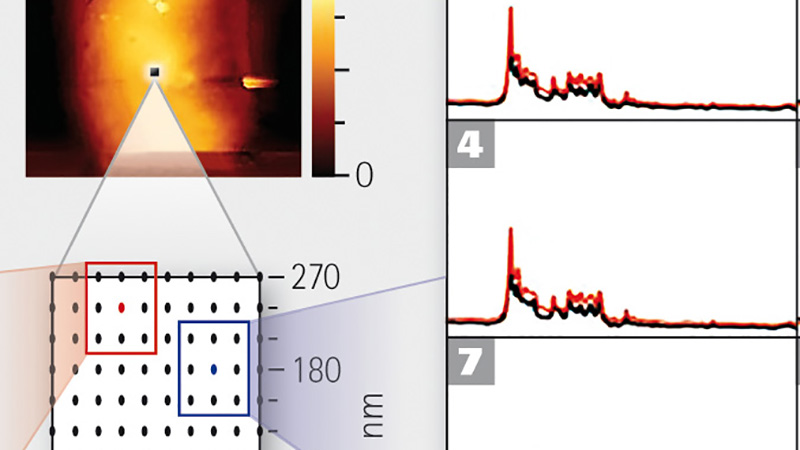
Using the sample scanner for imaging the specimen a region of interest (ROI) is confined. This area is then displayed in the image viewer of the JPK SPM software. For performing TERS measurements on this ROI it is necessary to switch to force spectroscopy mode. This is needful due to the fact that the TERS-tip has to be kept in close vicinity to the sample surface while the Raman signal is collected because of the exponential decay of the enhancing electromagnetic field of the metal coated tip. This is achieved by closed-loop controlled sample positioning of the TAOTM stage. In the force spectroscopy mode an arbitrary list or a grid of measurement points is applied for analysing the sample. The user-defined grid can be varied in size, number of point as well as point-topoint distance.
4. Data collection
After defining an area and the measurement points within the JPK SPM software, a script based communication between the AFM and the Raman PC is established. As a result of this the list of measurement points is recognized in the software of the Raman computer automatically. Subsequent the settings for the Raman acquisition and the start of the TERS measurements can be controlled within the Raman software.

Example data
For details see literature list
- Blood cells6
- RNA7
- Lipid bilayer8,9
- Cell membrane9,10
Conclusion
The marriage of an inverted Raman microscope with the NanoWizard® AFM and TAOTM module allows the simultaneous combination of topography and chemical information of transparent specimens with nanometer resolution. With this easy-to-operate setup users can achieve hassle free high spatial resolution Raman information. By the modular and flexible design of the JPK setup it is easily possible to upgrade any existing Raman spectrometer mentioned before. Implementing automated communication a very userfriendly data acquisition is enabled which brings the sensitivity and spatial resolution of Raman measurement to a next generation level.
Literature
- Stöckle R.M., et al, Nanoscale chemical analysis by tipenhanced Raman spectroscopy, Chem Phys Lett, 2000, vol. 318, 131 - 136
- Fleischmann M. et al, Raman Spectra of Pyridine adsorbed at a silver electrode, Chem Phys Lett, 1974 , vol. 26 (2), 163 - 166
- Wessel J., Surface-enhanced optical microscope, J Opt Soc Am B, 1985 , vol. 2 (9), 1538 - 1541
- Bailo E., Deckert V., Tip-enhanced Raman scattering, Chem Soc Rev, 2008 , vol. 37 (5), pp. 921
- Deckert-Gaudig T., Bailo E., Deckert V., Perspectives for spatially resolved molecular spectroscopy – Raman on the nanometer scale, J. Biophotonics, 2008, vol. 1 (5), 377 - 389
- Wood B. et al, Tip-Enhanced Raman Scattering (TERS) from Hemozoin Crystals within a Sectioned Erythrocyte, Nano Lett., 2011, vol. 11, 1868 – 1873
- Bailo E., Deckert V., Tip-Enhanced Raman Spectroscopy of Single RNA Strands: Towards a Novel Direct-Sequencing Method, Angewan. Chemie Int. Ed., 2008, vol. 47, 1658 – 1661
- Böhme R. et al., Biochemical imaging below the diffraction limit – probing cellular membrane related structures by tipenhanced Raman spectroscopy (TERS), J. Biophotonics, 2010, vol. 3(7), 455 - 461
- Böhme R. et al., Towards a specific characterisation of components on a cell surface – combined TERSinvestigations of lipids and human cells, J. Raman Spectrosc., 2009, vol. 40, 1452 – 1457
- Richter M., et al., Laterally Resolved and Direct Spectroscopic Evidence of Nanometer-Sized Lipid and Protein Domains on a Single Cell, Small, 2011, Vol. 7 (2), 209 - 214