Technical Note - Nanoscale Indentation: An Overview of Quasi-static Nanoindentation
Unlocking Material Insights with Precise and Reliable Quasi-Static Nanoindentation Testing
Nanoscale indentation or nanoindentation is a powerful technique used to quantitatively characterize the mechanical properties of small volumes of material. By fitting the appropriate models to the force vs. displacement curve obtained during the test, material properties such as elastic modulus, hardness, creep, stress relaxation, interfacial adhesion, and fracture toughness can be measured at the nanoscale and microscale.
Contents include:
KEYWORDS: Nanomechanical Test Instrument; Hysitron; Bruker; Tecnical Note; TN1500; Nanoindentation; Transducer; SPM Imaging
A quasi-static nanoindentation test is performed by applying and removing a load to a sample in a controlled manner with a geometrically welldefined probe. During the nanoindentation test, a force is applied by the transducer and the resulting displacement is observed to produce a traditional force vs. displacement curve (Figure 1). Bruker’s Hysitron® nanoindenters measures the force and displacement of the nanoindentation probe with a unique three-plate capacitive transducer design. This transducer design provides an unsurpassed noise floor and ultra-low working force.
The tightly controlled construction and calibration standards used for the capacitive transducer, in combination with the precisely machined, rigid nanoindentation probes, produce quantifiable and reliable measurements on any material. Analysis of the measured force vs. displacement curve (particularly the unloading segment) provides the user with information regarding the mechanical properties of the sample. Values typically obtained from quasi-static nanoindentation testing are reduced modulus (Er ) and hardness (H). However other information, such as fracture toughness, stiffness, delamination force, and film thickness also can be obtained.
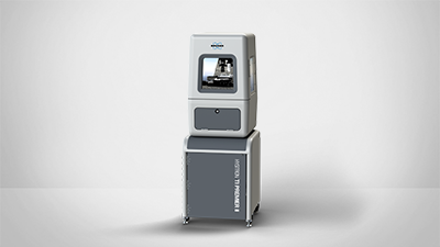
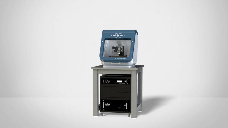
All Hysitron standalone nanoindentation systems are capable of in-situ SPM imaging. Using the same probe to scan a sample surface immediately before and/or after a test allows for precise placement of the test as well as near-instant observation of events or sample recovery
Quasi-static nanoindentation from Bruker is designed for maximum versatility. Standard with all Hysitron standalone nanoindentation systems and equipped with a standard maximum force up to 10 µN and a noise floor of less than 30 nN, quasi-static nanoindentation covers a large range of sample testing possibilities.
Quasi-Static Nanoindentation Data Analysis
Hysitron nanoindentation systems include a quasi-static data analysis package that uses a standard model1 to fit the initial unloading portion of the force vs. displacement curve to extract the reduced modulus (Er) and hardness (H) values. Quasi-static testing enables the nanoindentation probe area function to be calculated using an advanced analysis software package (Figure 2) to ensure any variations in probe geometry are accounted for.
How Quasi-Static Nanoindentation Works
Bruker’s nanoindentation transducer is unique in its operation and is the only system to use the three-plate capacitive design. Displacement is measured by running two AC signals that are 180° out of phase with each other to the top and bottom plate of the three-plate capacitive sensor. The AC signals are observed by the center (floating) plate and the sum of the signals corresponds to a measured displacement. To apply a load, a DC offset is applied to the lower plate of the transducer that electrostatically attracts the center plate downward. The resulting difference in the sums of the AC signals results in an offset in the sum of the AC signals, and thus a change in displacement (Figure 3).
References
- W. C. Oliver and G. M. Pharr, “An improved technique for determining hardness and elastic modulus using load and displacement sensing indentation measurements“, J. Mater. Res. 7 (6), 1564-83 (1992).
Hysitron is a trademark of Bruker Corporation. All other trademarks are the property of their respective companies. © 2018 Bruker Corporation. All rights reserved. TN1500, RevA0.


