Application Note: Strengthening Mechanisms of Copper in the Submicrometer Regime
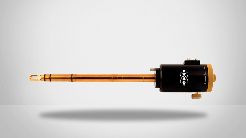
Investigating Size-Dependent Strengthening in Nano- and Microstructures using the Hysitron PI 95 TEM PicoIndenter
The mechanical properties of small volumes have been found to vary significantly from those of bulk for a wide range of materials. In bulk materials, there are several methods for increasing the strength, including work hardening and decreasing the grain size (Hall-Petch). This is in contrast to the two fundamental mechanisms that have been postulated as probable sources for the size-dependent strengthening in free-standing nano- and microstructures. Here, source truncation can be described as a size limitation of the Frank-Read dislocation source, where only a single pinning point operates as a spiral dislocation source. The stress for the spiral source to operate also depends on the proximity of the source to the surface. Spiral sources closer to the surface require greater energy to activate due to the required increase in curvature for the emitted dislocation. The second mechanism, the escape of dislocations to the surface of the material has been labeled a starvation/ exhaustion mechanism, reducing the number of available dislocation sources. This phenomena of decreasing dislocation density has been termed mechanical annealing, due to the dislocation density reduction achieved through thermal annealing in bulk samples. Both mechanisms were investigated in copper specimens using the Hysitron® PI 95 TEM PicoIndenter® instrument.
KEYWORDS: Copper; Direct-Pull; Tensile Testing; PI 95; TEM PicoIndenter; Push-to-Pull; Dislocations; Plasticity; FIB Milling
Direct-Pull Technique
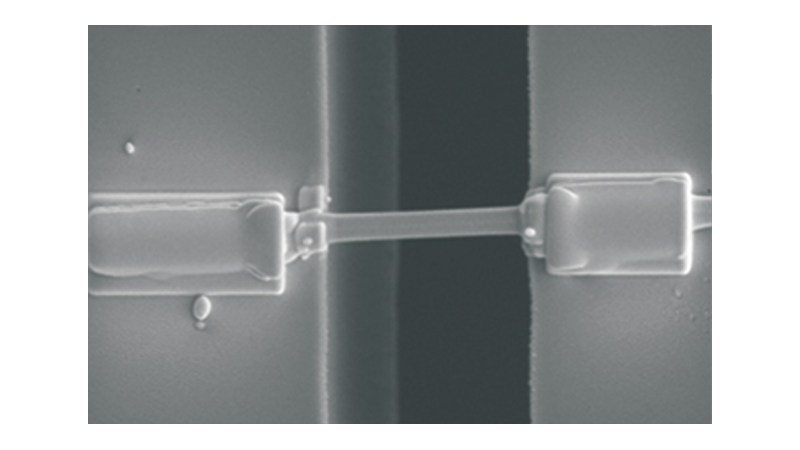
Two methods are available for uniaxial tensile testing using the Hysitron PI 95. The first technique, described here, consists of actuating the transducer in the reverse direction to apply tension directly to a specimen. This technique, which we refer to as “direct-pull”, is elegant but requires a gripping mechanism to couple the sample to the instrument, such as the dogbone specimens in Figure 1. The second technique employs an optional Push-to-Pull (PTP) MEMS device and is described elsewhere.
Experimental Setup
Copper (100) and (234) single crystal dogbone specimens were prepared using Focused Ion Beam (FIB) milling, with minimum gauge dimensions ranging from 128 to 190 nm. The gripper, designed as a counterpart to the dogbone shape, was milled via FIB from doped diamond (Figure 1). Both sample and gripper were milled with Ga+ ions at
30 keV with a final milling current of 10 pA, with a Pt coating applied to minimize FIB damage. Following fabrication, gripper and sample were mounted onto the Hysitron PI 95 and interfaced with a JEOL 3010 TEM. The gripper was then maneuvered into place around the dogbone specimen and a strain rate of ~5 x 10⁻³ s-1 was applied via a displacement-controlled mode. True stress and strain were determined through a combination of the load/displacement data and actual sample dimensions measured from the recorded TEM video. Yield stress was determined from the first large dislocation avalanche. The measurement was repeated for different sample sizes and crystal orientations and yield stress was plotted as a function of diameter and compared with the results of previous nanocompression and microtensile tests (Figure 2).
Dislocation Mechanisms
In the case of the single slip (234) oriented system, spiral dislocations were observed to form and bow out during the elastic loading. These dislocations were then pinned until the onset of plastic loading, which consisted of dislocations spiraling out of the source and piling up against other pinning points (Figure 3). As the dislocation back stress increased, the source was eventually shut down.
As the load applied by the Hysitron PI 95 increased, higher energy sources were activated, resulting in large bursts of dislocations and the creation of a slip step on the surface.
In addition to single uniaxial testing, the multiple slip, (100) oriented sample was loaded cyclically to investigate the stress strain behavior (Figure 4). The initial high dislocation density of 5.6±0.3x10¹⁴/ m-2 consisted of both surface dislocation loops, from the FIB fabrication, as well as internal dislocations. This dislocation density was seen to decrease by an order of magnitude throughout the course of six uniaxial cycles. This occurred with a corresponding increase in yield stress from 636 MPa to >2 GPa, indicating that a reduction in the dislocation density resulted in hardening, verifying a source exhaustion mechanism for increased yield strength.
Conclusions
The Hysitron PI 95 TEM PicoIndenter was used to perform direct-pull tensile tests on copper dogbone specimens. Both mechanisms, truncation and exhaustion, were observed to contribute to the deformation of the copper specimens. This investigation of the dislocation mechanisms fundamental to nanoscale plasticity is made possible through the combination of quantitative stress/ strain measurements with high-resolution TEM imaging.
Acknowledgements
Sourced from Source Truncation and Exhaustion: Insights from Quantitative in situ TEM Tensile Testing, D. Kiener and A. M. Minor, Nano Letters, 2011, 11 (9), pp 3816-3820; DOI: 10.1021/nl201890s.
Bruker Nano Surfaces Division is continually improving its products and reserves the right to change specifications without notice. Hysitron and PicoIndenter are trademarks of Bruker Corporation. All other trademarks are the property of their respective companies. © 2017 Bruker Corporation. All rights reserved. AN1504, Rev. A0


