Languages

nanoIR Spectroscopy Journal Club

High-Q Phonon-polaritons in Spatially Confined Freestanding α-MoO₃

by J. Yang, J. Tang, M. B. Ghasemian, M. Mayyas, Q. V. Yu, L. H. Li, and K. Kalantar-Zadeh

Key Points

  • Changing the dielectric environment has a dominant impact on the PhP propagation behavior;
  • Geometric confinement generated large Q factors of up to 40 in the freestanding area, which is 2−4 times higher than previously reported values; and
  • The findings from this work provide the foundation for guiding high-Q PhPs in α-MoO₃ at desired directions that can be potentially used for future nanophotonic and polaritonic devices.


 Receive future Journal Club updates via email.

This review appeared in the March 2022 edition of the nanoIR Journal Club — a monthly email brief highlighting leading-edge research and the latest discoveries supported by Bruker nanoIR technology.

ACS Photonics 2022, 9, 3, 905–913
DOI: 10.1021/acsphotonics.1c01726

α-MoO₃ is known to support highly confined and in-plane anisotropic phonon polaritons (PhPs). In the mid-IR regime, there exist three Reststrahlen bands (RB) for PhP generation, where the α-MoO₃ crystal exhibits negative permittivity along three principal axes. Compared to boron nitride and graphene, PhPs in α-MoO₃ have remarkably low loss that can lead to practical applications in waveguiding. In addition, PhPs in α-MoO₃ can be engineered by multiple factors, such as twisting the angle between adjacent layers and controlling the surrounding dielectric environment.

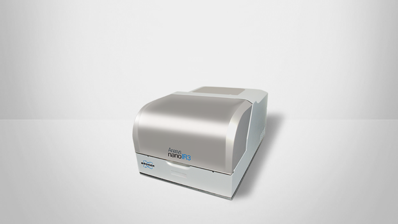
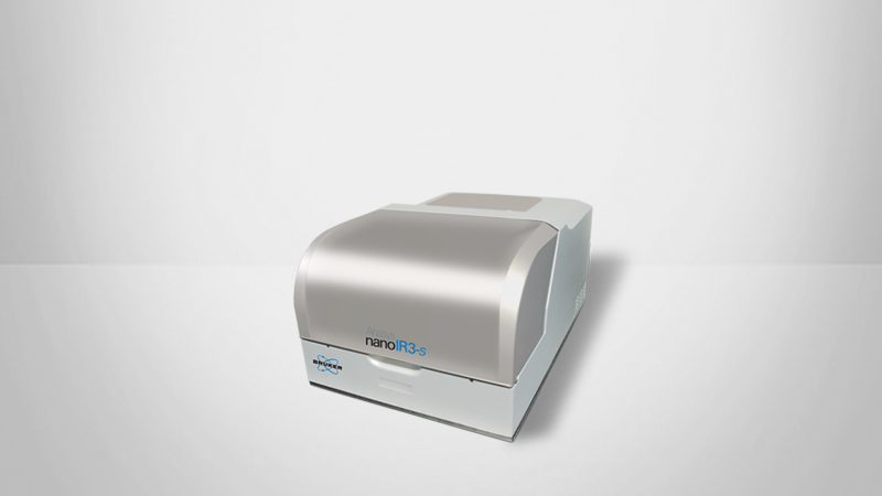
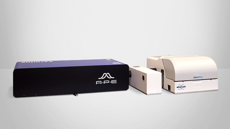
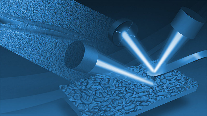
To investigate the impact of the dielectric environment pn PhP propagation, the authors used Bruker's nanoIR3-s with s‑SNOM to study thin flakes of α-MoO₃ placed on a SiO₂/Si substrate with prepatterned submicron trenches. The area of α-MoO₃ covering the trench is freestanding, while the rest is supported by the substrate.

The findings from this work provide the foundation for guiding high-Q PhPs in α-MoO₃ at desired directions that can be potentially used for future nanophotonic and polaritonic devices.


s-SNOM amplitude images showed:

  • PhPs propagating along the [100] direction in freestanding α‑MoO₃ have longer wavelength in RB2 and shorter wavelength in RB3 compared to their counterparts in supported α‑MoO₃;
  • Several samples with different widths and shapes of the freestanding areas displayed the opposite trend, indicating that the change of the dielectric environment has a dominant impact on the PhP propagation behavior; and
  •  Large Q factors of up to 40 in the freestanding area, which is 2−4 times higher than previously reported values and attributed to the geometric confinement.

To further demonstrate such impact, a circularly freestanding α-MoO₃ channel with submicron width was created and studied. s-SNOM imaging results showed that PhPs propagated along the curved trajectory.


Examination of angle-dependent PhP propagations* showed:

  • In RB2 with hyperbolic dispersion, PhP waves propagate along the freestanding α‑MoO₃ when the angle is small, and become less prominent in the freestanding area at large angles;
  • In supported α-MoO₃, PhPs propagate along the [100] direction;
  • In RB3 with elliptic dispersion, bright PhP propagation patterns were observed along the trench in freestanding α-MoO₃ for both small and large angles; and
  • In supported a-MoO₃, PhP fringes parallel to both the edge of α-MoO₃ and the trench were observed.

*by varying the angle (θ) of the trench relative to the [100] direction


      KEY TERMS:

  • α-MoO3; Geometric Confinement; NanoPhotonic Devices; Polaritonic Devices; Phonon-Polariton; Q Factor; s-SNOM; Waveguide